VHP Bio-Decontamination Systems
Cape Europe provides bespoke VHP bio-decontamination solutions from conception to qualification. We have designed and provided a number of systems for the bio- decontamination for applications of varying size and complexity from small volume rapid gassing transfer hatches to large pharmaceutical and research laboratories.
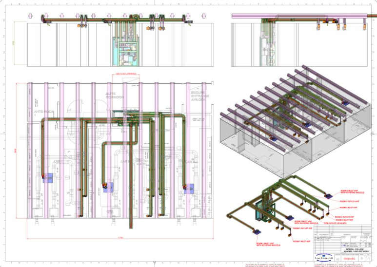
Designs are produced using the latest 3D computer aided design tools which facilitates the integration of the VHP distribution system with the building HVAC. 3D modelling techniques are ideally suited for providing quick and effective designs for VHP distribution systems.
Our team has system specification, system design, control engineering, build, qualification and project management expertise.
All systems are offered with full cGMP compliant qualification and validation packages.
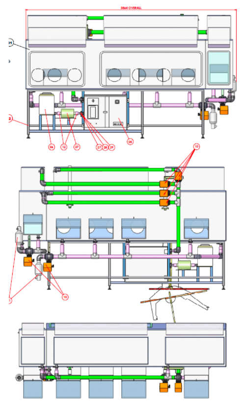
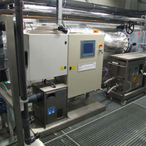
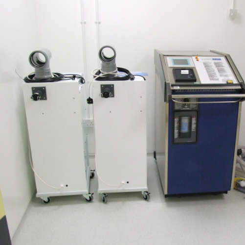
Example of a recent project for a fully automated VHP bio-decontamination system for a research facility comprising of a fixed VHP generator and distribution system supplying three separate laboratories.
VHP BIO-DECONTAMINATION SAPMLE SPECIFICATION
1 System overview
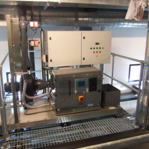
The design uses one Steris modular VHP generator mounted on skid along with a dehumidifier, inlet flow blower and system controller located centrally in the technical area connected to a network of distribution piping that supply a flow of VHP (vaporised hydrogen peroxide) to each of the of sets rooms which require VHP bio-decontamination. The generator is used in an open-loop by-pass configuration.
The system will be used for:
- 1.0 Bio-decontamination prior to planned maintenance or shutdowns of the volumes included in the document “list of rooms to be decontaminated”.
- 2.0 Bio-decontamination as part of a clean-up procedure following a spill in a lab.
- 3.0 Bio-decontamination of the labs following technical problems with the labs, HVAC, MBSCs or Isolators.
Vaporised Hydrogen Peroxide from the VHP generator is introduced into the dry air coming from the inlet blower via a by-pass. The resulting air/VHP mixture is then fed to each volume (room/airlock or transfer chamber) using the PVC pipe work distribution system. VHP is injected into each volume at different points via nozzles placed on the walls or on the ceiling. Where applicable VHP is also injected into the HVAC inlet ducts to decontaminate room inlet filters.
VHP exhausts from the volume during the bio-decontamination cycle via the HVAC exhaust ducting. Pressure in the room during the VHP cycle is controlled by the lab HVAC control system. The lab HVAC is used for final aeration to optimise overall cycle time.
The inlet blower speed and VHP cycle parameters are set by the VHP skid controller dependant on the volume selected.
2 VHP distribution pipe work
Distribution pipe work specification:
- Distribution - Leak tight uPVC grade E pipe work build and tested to Cape Europe specification TD125 (Cape technical document).
- Thermally insulated inlet piping.
- Room inlets - specially designed nozzles with positional adjustment and adjustable orifice plates to optimize turbulence in the room during bio- decontamination. The final position and flow rate of each orifice is set during cycle development.
3 Control overview
The skid controller HMI acts as the operator interface. The VHP generator is equipped with an HMI and printer. The generator HMI is used for entering VHP cycle parameters, maintenance and calibration. The printer is used to print cycle results and VHP configuration data.
The VHP HMI also allows the generator to be used independently if required.
The gas generator must be powered up and the main menu (standby) screen displayed for bio-decontamination to take place.
In the event of an alarm during the bio-decontamination cycle when hydrogen peroxide is present the VHP generator advances directly to the aeration phase of the bio-decontamination cycle until a Supervisory level operator re-sets the emergency stop. If an alarm occurs during dehumidification or and other part of the cycle where no peroxide is present the generator advances to cycle complete.
4 Cape Europe scope of supply
The VHP bio-decontamination system supplied by Cape Europe comprises of:
- VHP skid including the VHP generator, dehumidifier, inlet blower, by-pass valves.
- Supply and installation of the VHP distribution pipe work, and adjustable distribution nozzles.
- Testing, commissioning and IQ of the VHP skid.
- On site calibration and start-up of the VHP generator.
- Commissioning of the VHP system and testing of the functionality.
- IQ/OQ protocol and testing of the VHP distribution system.
- Cycle development of two example volumes combined with hands- on user training.
Documentation
All documents are supplied in English. The documents supplied with the system are:
- Full specification of the system (Functional Design Specification).
- Pipe work layout design (including 3D general arrangement drawings, sub assembly drawings and parts lists).
- Pipework specification.
- Validation Plan and list of commissioning/qualification protocols.
- Technical documentation.
- Commissioning protocol and report.
- Operators Manual.
5 Bio-decontamination system performance
The system is specified for lab conditions at the start of the cycle - temperature 18 - 35oC, RH 5 - 50%.
System performance is based on a leak rate for the labs equivalent to those given in the Clestra technical document TF86.1/SYLAB, dated 01.09.04 describing typical room leak rates for research lab constructions:
Leak rate expressed in lab volumes/h = 1.48 ~ 1.5Vols/h.
The bio-decontamination cycle is to achieve a 6 log reduction of Geobacillus Stearothermophilus ATCC 1298.
Largest volume to be bio-decontaminated = 400 m3. Smallest volume to be bio-decontaminated = 14 m3.
6 Process tolerances
The Steris tolerance on flow rates greater than 20m3.h-1 is +/- 3 m3.h-1 (calibration tolerance for the re-circulation blower).
The Steris tolerance for injection rates is +/- 20% of the set point for the first 3 minutes of injection followed by +/-10% for the rest of the phase duration. (Steris Technical memo dated 08jun.2004).
Humidity +/- 5% of set point. This parameter is determined by the performance of the Munters unit
Temperature +/- 3°C.